forked from dr.sybren/rignodes
ControlRig prototype for Blender
|
|
||
|---|---|---|
| __init__.py | ||
| .gitignore | ||
| execute.py | ||
| gui.py | ||
| LICENSE | ||
| mypy.ini | ||
| nodes.py | ||
| operators.py | ||
| README.md | ||
| rignodes-demo.blend | ||
| rignodes-leggy-suzanne.blend | ||
| rignodes-nodes-example.webp | ||
| rignodes-transfer.blend | ||
RigNodes
Node based control rig prototype for Blender.
Download & Install
- Be aware that this is a prototype.
- Download rignodes-main.zip
- Within Blender, go to Preferences, Add-ons, and use the 'Install...' button to install the ZIP.
- Enable the add-on.
Play around
- Add an Armature to your scene so you have something to control.
- Add some Empties to your scene to act as controls.
- Create a node tree in the RigNodes editor.
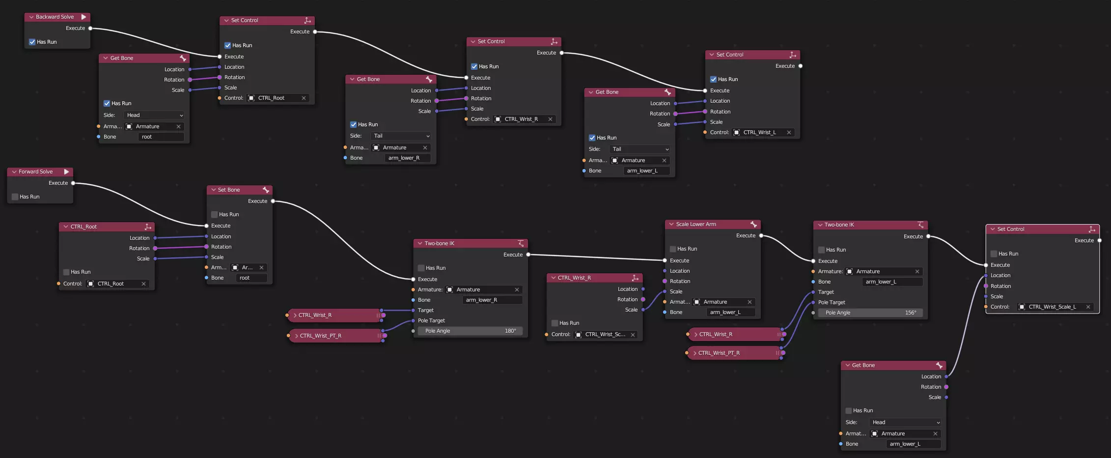
- Add a Forward Solve node and connect its Execute socket to other nodes. Be sure to keep this a single chain, i.e. only one link per socket.
- Add a Backward Solve node and create another sub-graph.
Design Principles
Not a complete list yet.
- Rotations are always quaternions. Conversion is OK, but if it's labeled "Rotation" it has to be a quaternion.
- All transforms are in world space, except when there is an explicit choice or conversion node.
- Nodes should try and produce 'normal' values. So a vector normalisation node should output
(0, 0, 0)for unnormalizable inputs, and a division by zero should produce0. When we have a 'debug mode' for visualising issues in the node tree, then we can outputNaNinstead, and highlight those sockets to help tracing those issues.
Optional vs. regular input sockets
In the code of certain nodes you'll find 'optional' input sockets. Those are for optional functionality of the node. If such a socket is unconnected, it will cause certain functionality to be skipped. For example, a "Set Bone" socket will only set the bone's rotation if the 'Rotation' socket is connected.
Note that these are not indicative of whether the socket must be connected or not. Regular input sockets can also remain unconnected. The big difference is that regular input sockets will allow users to edit their values when unconnected, whereas 'optional' sockets will not.
- Regular socket
- Always has a value. When unconnected, the GUI allows a user to edit the socket value.
- Optional socket
- Only has a value when connected. When unconnected, the corresponding functionality is simply skipped.
Wishlist
These nodes are wished for in the prototype. No promises.
- Execution sequencer (one Execute input, multiple outputs to run next)
NodeReroutesupport- Conditional execution (one Execute input, multiple outputs, enum property style choice of which output to run next)
- Input parameters for forward/backward solves, that can be set by whatever is triggering the solve (like manipulators)
- 'Draw Hierarchy' node that can draw an armature hierarchy in the 3D Viewport, as it is at that point in the node tree evaluation.
Event Nodes
- Forward Solve
- This is the main entry point for the tree when you move a control. The purpose of this event node is to take the control transforms and apply changes to bones.
- Backward Solve
- This is the main entry point for the tree when you move a bone. The purpose control this event node is to take the bone transforms and apply changes to controls.
Flow Control
- Sequence
- Splits the 'Execute' noodle into multiple, which are executed sequentially.
Bone Nodes
- Get Bone
- gets a bone's location, rotation, and scale. You can choose between the head and tail position. The transforms are expressed in world space.
- Set Bone
- sets a bone's location, rotation, and scale. Only influences things when the sockets are connected, i.e. leaving the rotation unconnected will keep the bone's rotation as-is. The transforms are interpreted as world space.
- Two-Bone IK
- performs IK on the named bone and its parent.
Controller Nodes
- Get Control
- gets a control's location, rotation, and scale. The transforms are expressed in either world space or 'channels space' (which is just the local location/rotation/scale properties).
- Set Control
- sets a control's location, rotation, and scale. Only influences things when the sockets are connected, i.e. leaving the rotation unconnected will keep the bone's rotation as-is. The transforms are interpreted as world space or 'channels space' (which is just updating the local location/rotation/scale properties).
Math Nodes
- Clamp
- clamps a value between a minimum and a maximum.
- Add / Subtract / Multiply / Divide
- performs a mathematical operation on its two inputs.
- To Euler
- converts a rotation (which is always a quaternion) to Euler angles. Its outputs are X/Y/Z values in degrees.
- From Euler
- converts Euler angles to a quaternion. Its inputs are X/Y/Z values in degrees.
Debug Nodes
- Set Cursor
- sets the 3D cursor to the given location/rotation. The transforms are interpreted as world space.
