Geometry Nodes: support attaching gizmos to input values #112677
No reviewers
Labels
No Label
Interest
Alembic
Interest
Animation & Rigging
Interest
Asset Browser
Interest
Asset Browser Project Overview
Interest
Audio
Interest
Automated Testing
Interest
Blender Asset Bundle
Interest
BlendFile
Interest
Collada
Interest
Compatibility
Interest
Compositing
Interest
Core
Interest
Cycles
Interest
Dependency Graph
Interest
Development Management
Interest
EEVEE
Interest
EEVEE & Viewport
Interest
Freestyle
Interest
Geometry Nodes
Interest
Grease Pencil
Interest
ID Management
Interest
Images & Movies
Interest
Import Export
Interest
Line Art
Interest
Masking
Interest
Metal
Interest
Modeling
Interest
Modifiers
Interest
Motion Tracking
Interest
Nodes & Physics
Interest
OpenGL
Interest
Overlay
Interest
Overrides
Interest
Performance
Interest
Physics
Interest
Pipeline, Assets & IO
Interest
Platforms, Builds & Tests
Interest
Python API
Interest
Render & Cycles
Interest
Render Pipeline
Interest
Sculpt, Paint & Texture
Interest
Text Editor
Interest
Translations
Interest
Triaging
Interest
Undo
Interest
USD
Interest
User Interface
Interest
UV Editing
Interest
VFX & Video
Interest
Video Sequencer
Interest
Virtual Reality
Interest
Vulkan
Interest
Wayland
Interest
Workbench
Interest: X11
Legacy
Blender 2.8 Project
Legacy
Milestone 1: Basic, Local Asset Browser
Legacy
OpenGL Error
Meta
Good First Issue
Meta
Papercut
Meta
Retrospective
Meta
Security
Module
Animation & Rigging
Module
Core
Module
Development Management
Module
EEVEE & Viewport
Module
Grease Pencil
Module
Modeling
Module
Nodes & Physics
Module
Pipeline, Assets & IO
Module
Platforms, Builds & Tests
Module
Python API
Module
Render & Cycles
Module
Sculpt, Paint & Texture
Module
Triaging
Module
User Interface
Module
VFX & Video
Platform
FreeBSD
Platform
Linux
Platform
macOS
Platform
Windows
Priority
High
Priority
Low
Priority
Normal
Priority
Unbreak Now!
Status
Archived
Status
Confirmed
Status
Duplicate
Status
Needs Info from Developers
Status
Needs Information from User
Status
Needs Triage
Status
Resolved
Type
Bug
Type
Design
Type
Known Issue
Type
Patch
Type
Report
Type
To Do
No Milestone
No project
No Assignees
4 Participants
Notifications
Due Date
No due date set.
Dependencies
No dependencies set.
Reference: blender/blender#112677
Loading…
Reference in New Issue
No description provided.
Delete Branch "JacquesLucke/blender:geometry-nodes-gizmos"
Deleting a branch is permanent. Although the deleted branch may continue to exist for a short time before it actually gets removed, it CANNOT be undone in most cases. Continue?
This adds support for attaching gizmos for input values. The goal is to make it easier for users to set input values intuitively in the 3D viewport.
We went through multiple different possible designs until we settled on the one implemented here. We picked it for it's flexibility and ease of use when using geometry node assets. The core principle in the design is that gizmos are attached to existing input values instead of being the input value themselves. This actually fits the existing concept of gizmos in Blender well, but may be a bit unintutitive in a node setup at first. The attachment is done using links in the node editor.
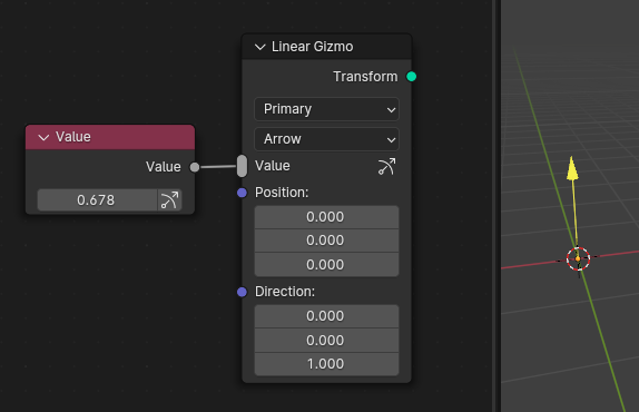
The most basic usage of the node is to link a Value node to the new Linear Gizmo node. This attaches the gizmo to the input value and allows you to change it from the 3D view. The attachement is indicated by the gizmo icon in the sockets which are controlled by a gizmo.
The core principle makes it straight forward to control the same node setup from the 3D view with gizmos, or by manually changing input values, or by driving the input values procedurally.

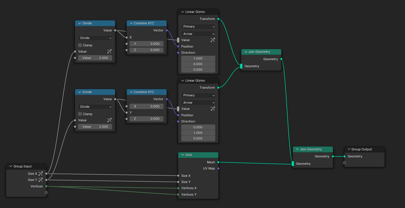
If the input value is controlled indirectly by other inputs, it's often possible to automatically propagate the gizmo to the actual input.

If it's not possible to propagate the gizmo, the icon will be grayed out a bit. This can happen when the nodes the gizmo should be propagated through don't have an (approximate) inverse function or Blender does not know it yet. Some reverse functions may still be added over time, but sometimes that's just not possible. In those cases, the gizmo would often not be useful anyway. If a gizmo is still desired, a new gizmo has to be created that is attached to the actual input directly.

This patch adds the first two gizmo nodes which cover basic but common use cases:
In the future, more built-in gizmos and potentially the ability for custom gizmos could be added. Potential built-in gizmos could e.g. control a full 3D rotation, a position in space or a bounding box. These can kind of be build from lower level gizmos like the ones provided already, but not in a way that feels really well integrated.
All gizmo nodes have a Transform geometry output. Using it is optional but it is recommended when the gizmo is used to control inputs that affect a geometry. When it is used, Blender will automatically transform the gizmos together with the geometry that they control. To achieve this, the output should be merged with the generated geometry using the Join Geometry node. The data contained in Transform output is not visible geometry, but just internal information that helps Blender to give a better user experience when using gizmos.
The gizmo nodes have a multi-input socket. This allows controlling multiple values with the same gizmo.
Only a small set of gizmo shapes is supported initially. It might be extended in the future but one goal is to give the gizmos used by different node group assets a familiar look and feel. A similar constraint exists for colors. Currently, one can choose from a fixed set of colors which can be modified in the theme settings. The scale of the gizmo can not be edited yet. This can be added separately whereby we have to differentiate between gizmos that are scaled in screen spaces and those scaled object space.
The set of visible gizmos is determined by a multiple factors because it's not really feasible to show all possible gizmos at all times. To see any of the geometry nodes gizmos, the "Active Modifier" option has to be enabled in the "Viewport Gizmos" popover. Then all gizmos are drawn for which at least one of the following is true:
Potential future improvements:
Links:
@blender-bot package
Package build started. Download here when ready.
@blender-bot package
Package build started. Download here when ready.
@blender-bot package
Package build started. Download here when ready.
@blender-bot package
Package build started. Download here when ready.
@blender-bot package
Package build started. Download here when ready.
@blender-bot package
Package build started. Download here when ready.
Remaining design topics IMO:
Overall I found the code pretty nice. My one larger concern is the growing extent to which we're adding specific code in places that are just general for the entire node system. I didn't get to the gizmo propagation code yet.
@ -680,6 +691,7 @@ class NODE_MT_geometry_node_add_all(Menu):layout.menu("NODE_MT_category_GEO_TEXTURE")layout.menu("NODE_MT_category_GEO_UTILITIES")layout.separator()layout.menu("NODE_MT_category_GEO_GIZMO")Might as well hide this for tools
@ -14,3 +16,4 @@#include "BLI_bounds_types.hh"#include "BLI_function_ref.hh"#include "BLI_map.hh"#include "BLI_math_matrix_types.hh"BKE_geometry_set.hhis a fairly common header, it would be nice to avoid the need to include these two headers here. Putting them in a separate class / header likeCurvesEditHintsandGreasePencilEditHintswould make sense I think.@ -133,6 +136,7 @@ class bNodeTreeRuntime : NonCopyable, NonMovable {/** Information about usage of anonymous attributes within the group. */std::unique_ptr<anonymous_attribute_inferencing::AnonymousAttributeInferencingResult>anonymous_attribute_inferencing;std::unique_ptr<nodes::gizmos::GizmoPropagationResult> gizmo_inferencing;I don't really expect anything to change in this PR necessarily, but I find it really ugly how we keep adding these geometry nodes specific things into the base node tree runtime class. I think it adds confusion about the responsibility of different code. It would be better to generalize this a bit. But maybe that depends on our end goal for what node tree types are supposed to mean. Just deserves some active thought IMO.
Hm, I don't really have a problem with it in this specific case. I haven't found a case where it actually hurts us (at least in run-time data). We could move the geometry nodes specific stuff to a separate struct, but it's not clear to me whether that makes the code better or just more verbose.
@ -199,0 +204,4 @@* This is set in #update_gizmo_propagation and is stored here so that it can be quickly accessed* during socket drawing.*/bool has_gizmo = false;Storing this specific data in general structs is a serious anti-pattern IMO. 99% of the time this isn't needed, and it isn't related to anything else here.
Maybe it would work to store something in
GizmoPropagationResultinstead. Maybe aBitVectoror aSet<int>Last time we tried something like that with
location, it didn't work out. Not sure if that situation has really changed. If it did, I'm fine with moving this data to a separate array, but I'm not willing to risk that as part of this patch. We can try that separately again.@ -97,1 +97,3 @@uiItemR(layout, &sockptr, "default_value", DEFAULT_FLAGS, "", ICON_NONE);uiLayout *row = uiLayoutRow(layout, true);uiItemR(row, &sockptr, "default_value", DEFAULT_FLAGS, "", ICON_NONE);if (output->runtime->has_gizmo) {I guess this is covered by my other comments, but I find myself skeptical of the gizmo checks creeping in this far, running even in shader nodes, for example. It just seems like a hack. Some alternatives I could think of:
For generic socket drawing it's probably worth generalizing this more as well
I think on a conceptual level, an "extra button" callback for nodes and sockets would make sense here. However, it seems like this would not actually give us the control we want. For a better looking ui it's probably better to define how it's drawn in one place instead of two, especially because the ui elements belong closely together.
I see this somewhat similar to property decoration for creating keyframes.
With this additional callback, it wouldn't be so clear whether you should pass in
layoutorrow, both are constraining in different ways.@ -0,0 +76,4 @@if (prop_type == PROP_FLOAT) {return RNA_property_float_get_index(&this->owner, this->property, *this->index);}else if (prop_type == PROP_INT) {Else after return
@ -0,0 +137,4 @@RNA_property_update(C, &this->owner, this->property);if (Object *object = CTX_data_active_object(C)) {/* The recalc is necessary so that the gizmo positions are updated even if they don't affect* the final output currently. */Do you have an idea for how this could be fixed? Maybe just tagging the region for redraw could work?
Removed it for now. Couldn't reproduce the purpose anymore, but not sure if I really fixed it already or just don't know how to reproduce the issue anymore. If we'll need it again, it can also use
DEG_id_tag_update_for_side_effect_request.@ -0,0 +158,4 @@const bNodeSocket &second_input_socket = node.input_socket(1);const float second_value =tree_log.find_primitive_socket_value<float>(second_input_socket).value_or(0.0f);switch (mode) {Looks so nice without the brackets :D
@ -253,1 +253,4 @@}if (geometry.get_component<GeometryComponentEditData>()) {auto &component = geometry.get_component_for_write<GeometryComponentEditData>();for (float4x4 &m : component.gizmo_transforms_.values()) {Just curious, do you imagine that other nodes would end up being able to deform the gizmo transforms?
Note sure about the existing nodes, but I could imagine that we could add nodes that allow deforming the transforms. It's quite similar to what we talked about for crazy space for curves.
@blender-bot package
Package build started. Download here when ready.
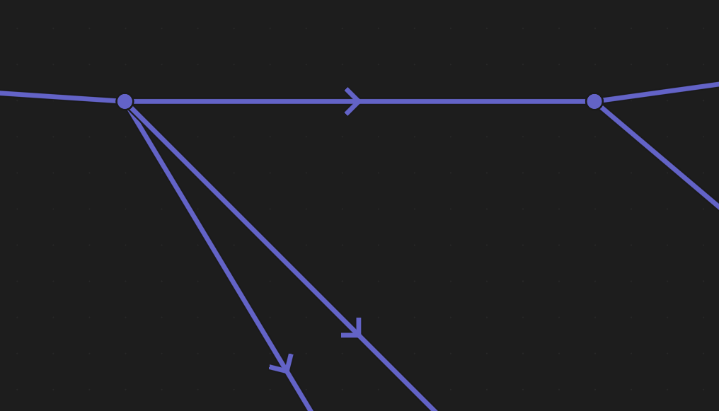
I do after multiple considerations feel like there should be some (subtle) difference in drawing for the links that propagate the gizmo control backwards in addition to the icons on the sockets that do so.
When working on an example setup I found multiple instances where it gets confusing quite quickly how the gizmo control is flowing in the graph. The icons
docan in theory communicate the complete information, but practically they are not sufficient since, when working on a node-tree, you don't always have all nodes in your view at all times, nor should you have to, to understand the information presented.Case where the icons right now are not sufficient:

Is X and Y or either one used for the gizmo control?
Case where it's ambiguous which connection controls the group input:

Is one connection a gizmo or both? Which one is it?
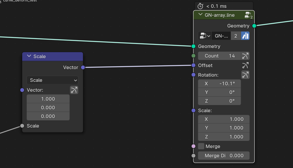
And this might look like a stupid example, but having to scan all the connected nodes between on or potentially multiple reroutes that don't even have an icon themselves is a lot of overhead:
And again, I realize that only showing a part of the node-tree is not looking at all the information it provides, but understanding the dataflow should ideally not rely on seeing all the context. That's a big readability issue imo, that we are already fighting with the evaluation of fields, where you need to scan a lot of the node-tree to understand what is happening, rather than having all that context locally visible.
In a practical sense, looking at all the connected nodes first, which might be quite far away is quite inconvenient when you need this information to understand the context of the gizmo icon in the node.
One question that might alleviate the issue of presenting potentially irrelevant information and making the node-tree more noisy that it might need to be:
Would it be possible to only draw the links differently whenever the gizmos are actually drawn? That way, in most of the cases where the gizmo back propagation is something you don't care about the node-tree wouldn't look any different then now. The icons would still be there. But then it would be more like showing the flow when it matters. Just an idea.
I wonder, how would knowing which links in your examples propagate a gizmo affect what you do? Knowing where a link goes helps of course, but that doesn't seem unique to gizmos at a first glance.
Seems possible, but I wonder if that is good enough. It doesn't seem to help in the example you showed if the gizmo isn't visible already.
I mean, the fact that you have to understand how the control of a gizmo is propagated back is not in question, is it? It's pretty important when setting up how the node-tree is being controlled to understand these connections. It's pretty important when connecting the a node link to see that this also means it will be controlled by a gizmo, potentially a second or third gizmo if you are connecting the value in multiple places. It's not so much changing my actions in how I connect the nodes, but more so giving me clear insight into the implications of my actions.
As an example, if I have a node in my node-tree that uses gizmos for the inputs and I connect something to one of these inputs, the gizmo is still usable to control the value that this link propagates the information to. This should be clearly visible from the node that shows this connection imo.
Scanning every connected node with your eyes to find the string of connected nodes with the icon is not a valid replacement for making this clearly readable imo.
Exactly, my thought process was that in the cases that the gizmo isn't visible, you usually do not care about the propagation. Changing the drawing of the connected links that propagate the gizmo information when you select a node and makes its gizmos visible would also highlight that the gizmos that are now showing up will propagate changes in your node-tree.
That part could also be indicated by graying out the gizmo icon when the gizmo is "broken" because it's controlled in a way that does not support a gizmo I think.
Hm ok, I can give this a try.
That's a good idea, but it's not actually what I meant. I just meant the totally valid case that I've shown in the screenshot. I think it's a lot more clear that the gizmos will have an effect on other values in your node-tree that the active node is connected to when the links indicate the flow of that control.
Another example would be wanting to manually control the value precisely, that you just set by eye in the viewport. Finding the actual value that has been modified is a lot easier if you can visually track the connections.
WIP: Geometry Nodes: add support for gizmosto WIP: Geometry Nodes: attaching attaching gizmos for input valuesWIP: Geometry Nodes: attaching attaching gizmos for input valuesto WIP: Geometry Nodes: support attaching gizmos for input valuesWIP: Geometry Nodes: support attaching gizmos for input valuesto WIP: Geometry Nodes: support attaching gizmos to input valuesThat seems feasible. Will require a bit of refactoring, but probably not too much. Evaluating just the gizmo nodes that control operators inputs, without computing everything else is possible. Not sure if it will be required to disable that behavior in some cases since it has the potential to be slow.
@blender-bot build
WIP: Geometry Nodes: support attaching gizmos to input valuesto Geometry Nodes: support attaching gizmos to input values@blender-bot package
Package build started. Download here when ready.
@blender-bot package
Package build started. Download here when ready.
@blender-bot build
@blender-bot package
Package build started. Download here when ready.
Checkout
From your project repository, check out a new branch and test the changes.